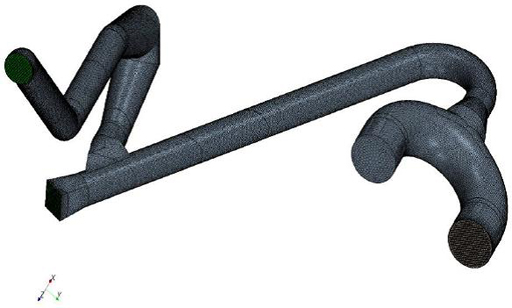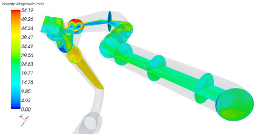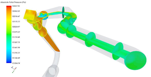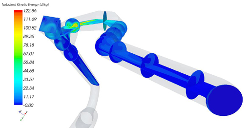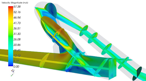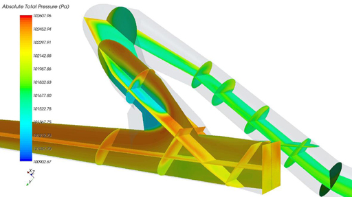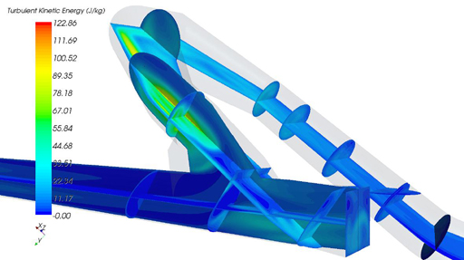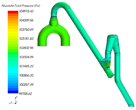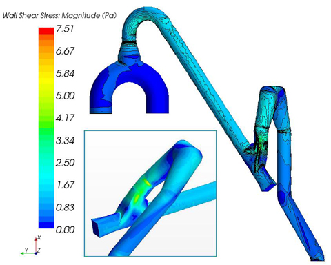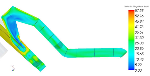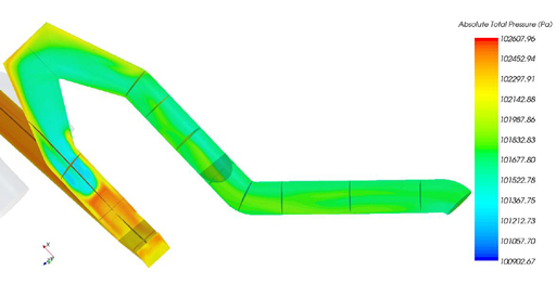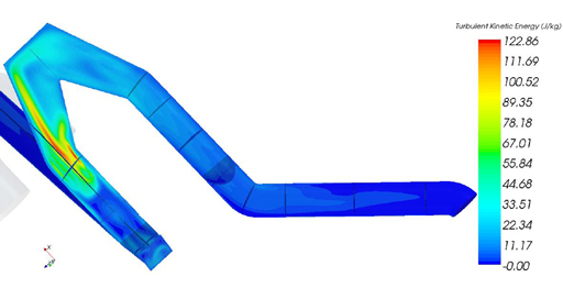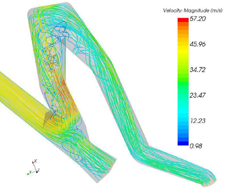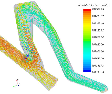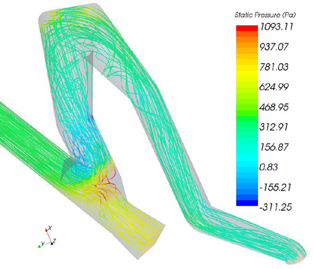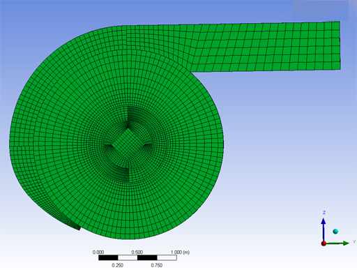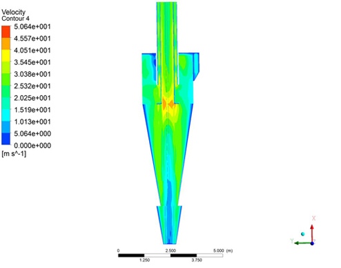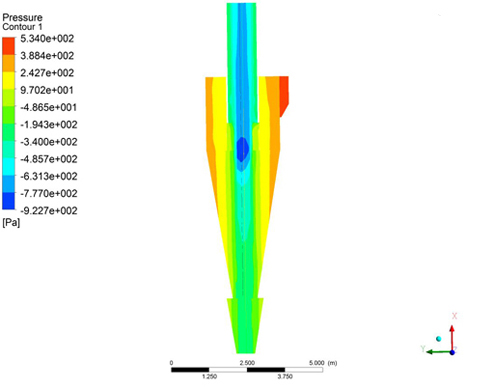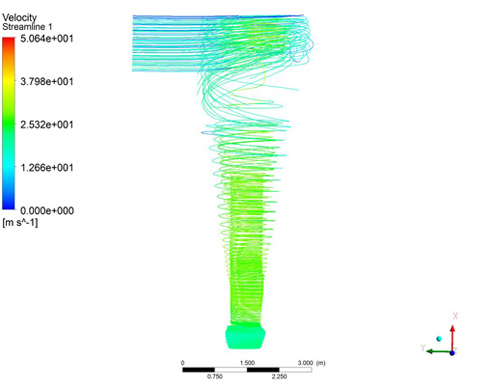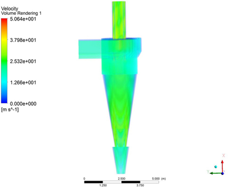
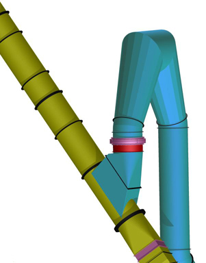
CFD uses numerical methods to predict fluid flow and related physical processes within a defined geometry. It provides detailed insight into flow and temperature distributions that can be difficult to capture with plant measurements alone.
How CFD Supports Engineering
- Visualize three-dimensional flow and temperature fields.
- Compare designs and operating conditions before making physical changes.
- Identify opportunities to improve equipment design and operation.
- Support more focused research, development, and testing.
Model assumptions, input data, and comparison with available plant measurements are important when interpreting results.
Explore the CFD applications below.
CFD Applications
Potential benefits depend on plant conditions and the changes implemented.
Gas Duct Modeling
Evaluate duct arrangements, geometry, and gas mixing.
- Reduce pressure drop, erosion, and material buildup.
- Improve flow distribution and the inlet conditions of mills, fabric filters, and fans.
- Improve mixing of gas streams at different temperatures.
Cyclone Modeling
Assess cyclone geometry and gas–particle flow.
- Improve particle collection efficiency.
- Evaluate pressure drop and wear.
- Understand internal flow and separation behavior.
Calciner Modeling
Evaluate burner locations and settings, SNCR lance positions, material distribution, and calciner geometry.
- Improve combustion and alternative fuel utilization.
- Identify opportunities to reduce specific fuel consumption and increase production.
- Improve process stability and raw meal distribution.
- Evaluate pressure drop, material buildup, and refractory exposure.
- Assess NOₓ, CO at the calciner exit, and SNCR reagent consumption.
Kiln Modeling
Evaluate kiln hood geometry, burner design, fuel fineness, and heat transfer.
- Improve combustion and heat transfer.
- Assess refractory exposure and potential causes of premature damage.
- Develop a better understanding of kiln operation.
Water Spray Systems
Evaluate system geometry and spray-lance locations.
- Improve gas distribution and water evaporation.
- Assess atomization and potential material buildup.
- Understand the interaction between sprays and gas flow.
Fabric Filters
Evaluate gas distribution through the filter.
- Improve flow distribution and support longer bag service life.
- Reduce pressure drop and localized wear.
Selective Non-Catalytic Reduction (SNCR)
Evaluate reagent-lance locations, the number of lances, injection-zone temperature, and duct geometry.
- Improve reagent distribution and use.
- Support NOₓ reduction.
- Assess material buildup and operating behavior.
Burner Systems
Evaluate burner design, location, fuels, and fuel fineness.
- Improve combustion and heat transfer.
- Assess refractory exposure and potential causes of premature damage.
Information Needed For The Assessment
Geometry, flow rates, temperatures, pressures, material or fuel properties, and the operating cases to compare. Available plant measurements help establish boundary conditions and assess the model.
What The Study Delivers
Flow and temperature visualizations, pressure-loss or mixing assessments appropriate to the scope, comparisons of design alternatives, and recommendations tied to the operating objective. Predictions are interpreted with the assumptions and available validation data.